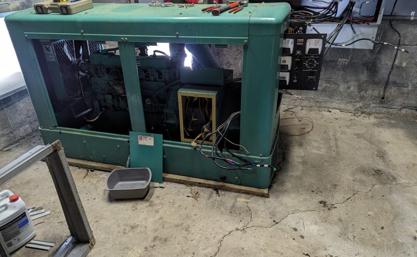
This Onan 30OEK propane-powered generator has been in service for 39 years at a transmitter site where the power goes out often. It has a lot of hours on it. The hour meter stopped working about 15 years ago, but the hours back then were 1097.
In addition, the main shaft seal started leaking oil about 10 years ago, creating an oily blowback mess every time the generator ran for more than a few hours. The block heater went bad, the battery charger overcharged then exploded the battery splashing sulfuric acid all over the housing and engine block.
The last power outage was the final one. It ran for a few hours then faulted. When the local engineer tried to restart it, it was never able to get to speed and was misfiring badly. Below appeared a large and spreading puddle of engine oil.
As this station is one of the major money makers for the owner, a replacement generator was obtained.
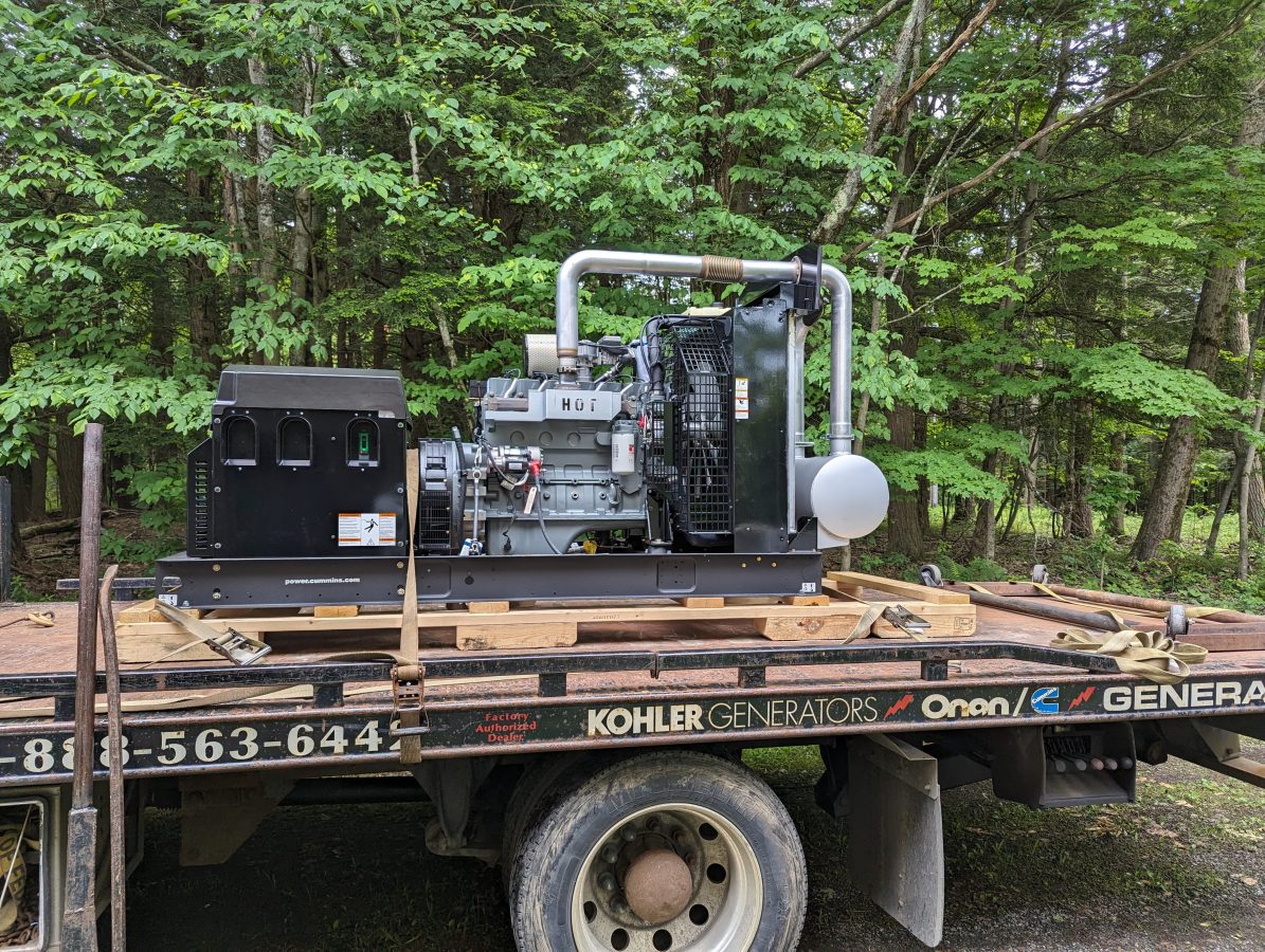
Cummins RS50 50 KW Propane powered generator
This is larger than the old generator. The good news; now the AC can be put on the generator to keep the room cool. In the past, the backup cooling fan was used when on generator power, which sucked dirt, bugs, and pollen into the room.
It will also have considerable headroom for any additional loads that may be installed in the future.
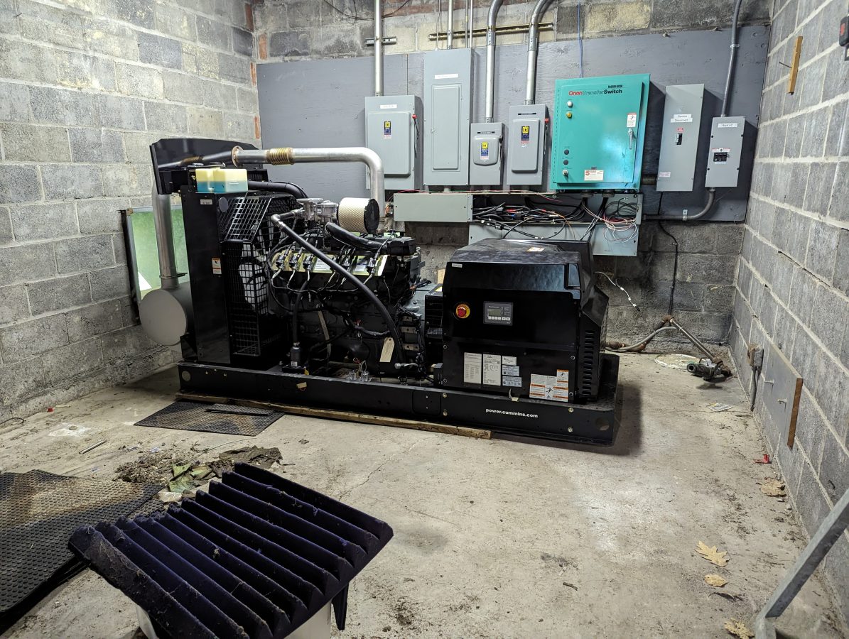
The generator in place and leveled
We had to enlarge the opening for the radiator and put in some steel angle for the lintels.
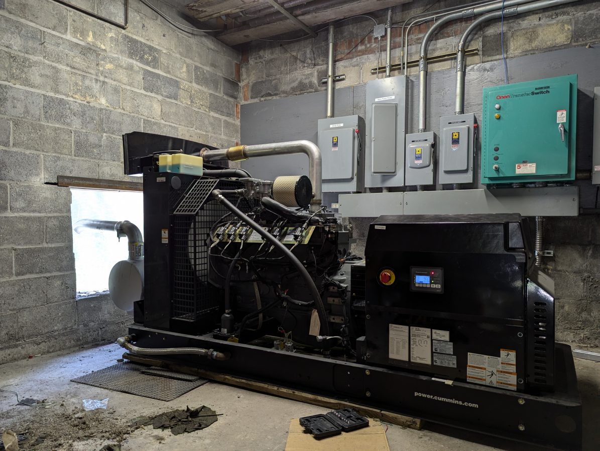
Exhaust piped outside with the radiator air
The first start run and load test went well. I ran it for about 30 minutes under full load, enough time to burn the paint off the exhaust manifold. Seems like a pretty solid unit. With the power conditions at this site, it will get a lot of use.
The antennas are the most interesting aspect of Radio Frequency Engineering to me. The transfer of power in the form of voltage and current to the magnetosphere and back again is where the rubber meets the road. Any opportunity to experiment with the art of antenna design and fabrication is welcome.
This is for the Amateur Radio community. With the upswing of Solar Cycle 25, predicted to peak in July of 2025, I decided it would be fun to get back on the air with some type of HF setup.
My past experience with HF radio and peak solar cycles is that wild fluctuations can occur creating band openings at unusually high frequencies or no propagation at all. The geek in me finds this very interesting. HF Propagation is a complex matter. Long-distance communication can be carried out with very low power levels provided the ionosphere is bouncing signals back to the earth instead of absorbing them.
Weak Signal Propagation Reporter (WSPR) is an HF beacon system, where stations transmit a digital signal containing your call sign and Maidenhead Gird locator for several seconds. The challenge is to have an efficient antenna and use as little power as possible. In this case about 200 mW (0.2 watts) or 23 dBm. The modulation type is MFSK and the bandwidth is 6 Hz. According to Wikipedia, which is mostly accurate about things like this; WSPR uses a transmission protocol called MEPT_JT. That sends messages composed of:
28 bits for callsign, 15 bits for locator, 7 bits for power level, total: 50 bits.
Forward error correction (FEC): non-recursive convolutional code with constraint length K = 32, rate r = 1⁄2.
Number of binary channel symbols: nsym = (50 + K − 1) × 2 = 162.
Keying Rate is 12000 ⁄ 8192 = 1.4648 baud.
Modulation is continuous phase 4 FSK, with 1.4648 Hz tone separation.
Occupied bandwidth is about 6 Hz.
Synchronization is via a 162-bit pseudo-random sync vector.
Each channel symbol conveys one sync bit (LSB) and one data bit (MSB).
Duration of transmission is 162 × 8192 ⁄ 12000 = 110.6 s.
Transmissions nominally start one second into an even UTC minute: e.g., at hh:00:01, hh:02:01, etc.
Minimum S/N for reception is around –34 dB on the WSJT scale (2500 Hz reference bandwidth).
Distant stations report reception to a database. Several good websites display reception in a map or table format.
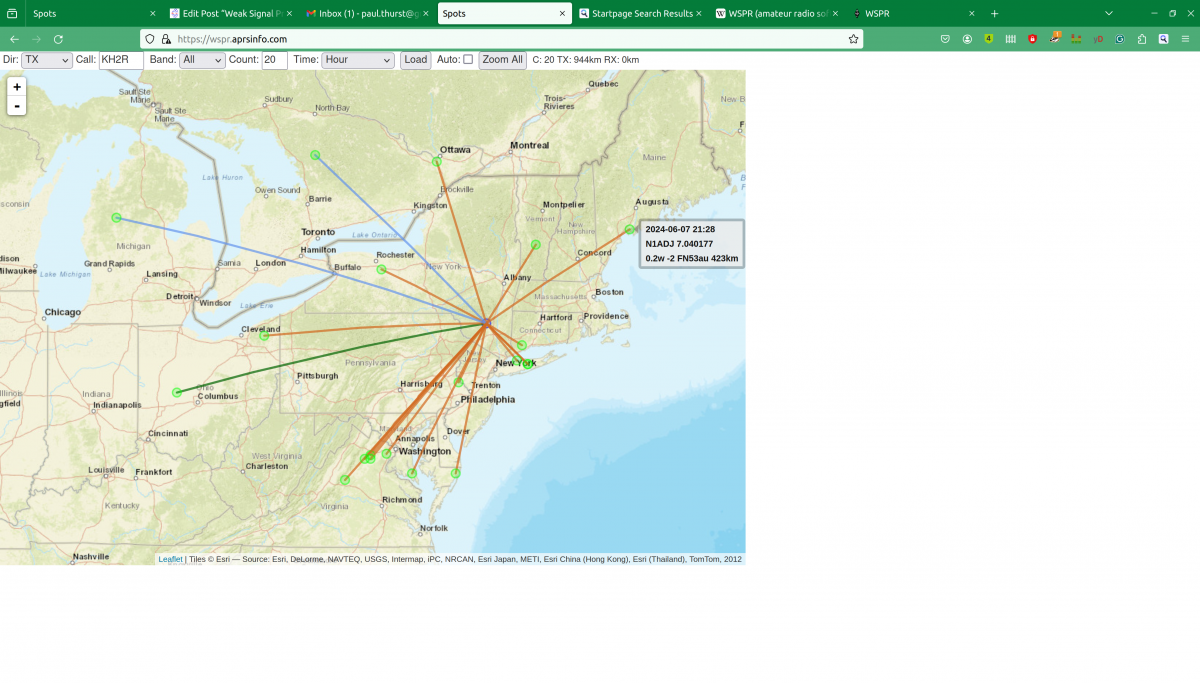
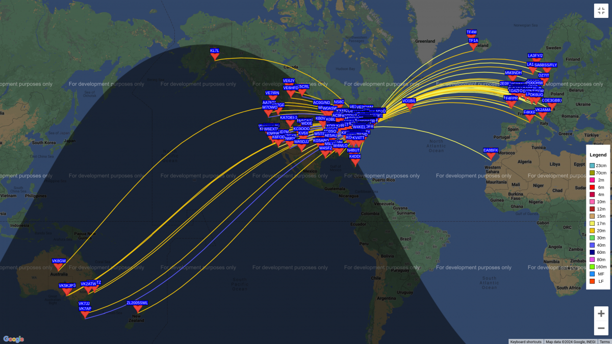
WSPR report
This map shows a good path to coastal Maine on 40 meters. The received signal-to-noise ratio is -2 dB at a distance of 423 KM.
80 Meter End Fed Half Wave antenna supported by trees
My antenna is an End Fed Half Wave (EFHW) cut to 3.568 MHz which can be used on any harmonically related frequency (7, 10, 14, 18, 21, 24, and 28 MHz). To accomplish this, a 49:1 Unun (Unbalanced feed to unbalanced feed) transformer is used to transform the 2,400-ohm impedance of the wire to the 50-ohm impedance required by the transmitter. The antenna works best against a ground system that is not less than 0.05 wavelength or 18 electrical degrees on its lowest frequency. That works out to about 4.2 meters (14 feet). A little bit longer is a little bit better. Six 20-foot long 14 gauge bare copper ground radials are attached to an 8-foot ground rod.
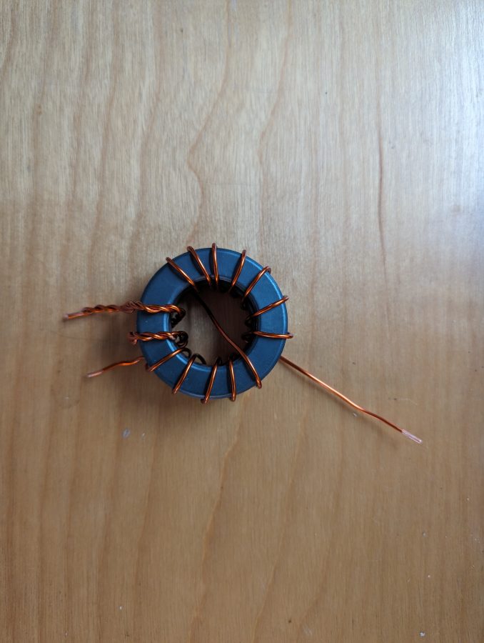
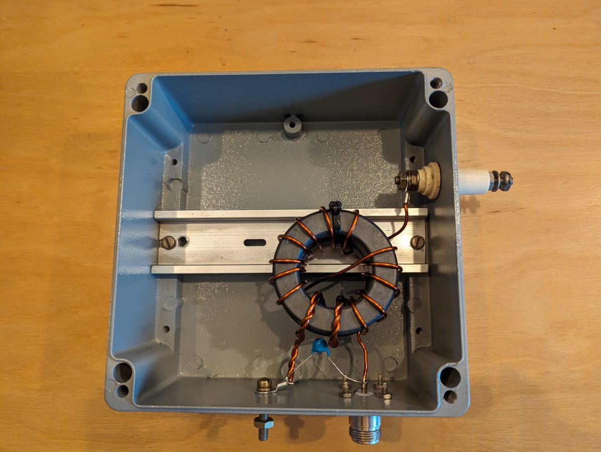
Diecast aluminum box containing 49:1 Unun
The Unun is two FT240-52 (not an affiliate link) cores with 14 gauge enamel wire consisting of 2 turns on the primary and 14 turns on the secondary. The antenna is 40 meters (132 feet) of 10 gauge hard-drawn stranded copper wire. This should be good for about 800 watts CW/SSB on HF if I want to use it in that capacity.
Unun transformerUnun wire tied to a DIN rail with 100 pF 5 KV capacitor
There are several guides on how to make the unun available via Google search. There is some debate on whether a 64:1 transformer should be used. Most indicate a 49:1 is the best match. The diecast aluminum (not an affiliate link) enclosure is a nice feature. It cost $33.00 on Amazon.
I used the network analyzer to trim up the antenna a bit. I made a few measurements, the first was just the wire with no ground connected. The next was the wire and ground system after trimming the length for resonance on 3.5 MHz.
The transmission line is LMR-400 with N connectors. I loath PL-259s and use N connectors whenever possible.
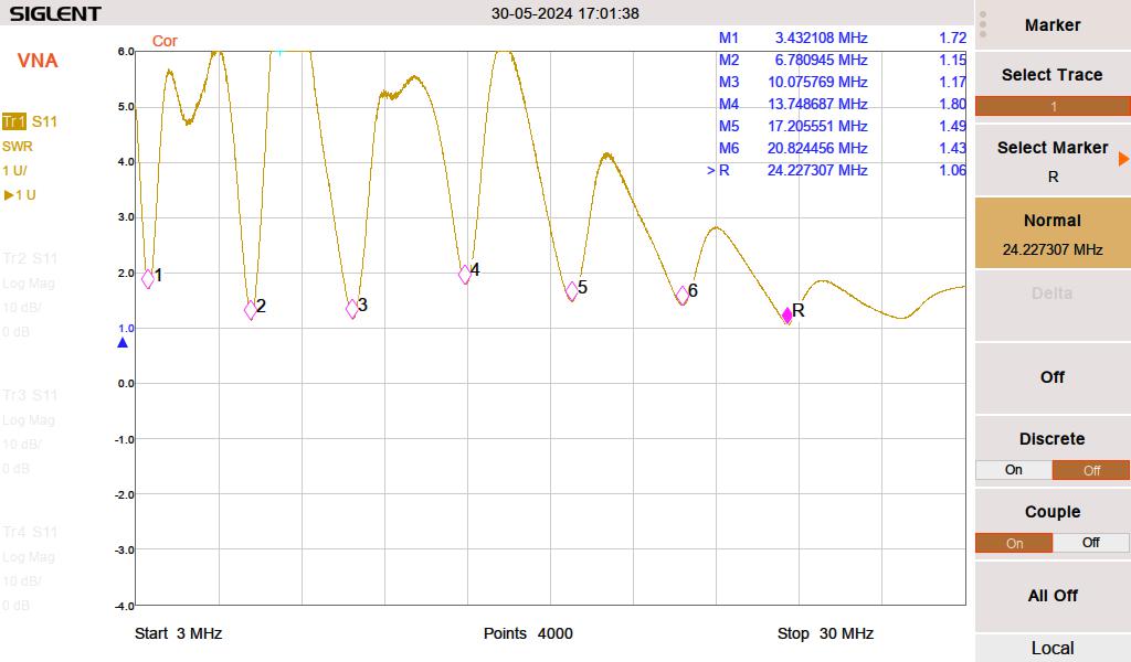
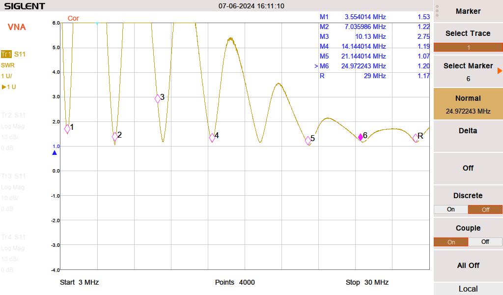
I did a series of broadband SWR sweeps. The first was just the wire prior to trimming.
First sweep, frequencies are a little low, SWR is a little high
The next was with a ground rod and six ground radials, #14 bare copper wire twenty feet long.
EFHW trimmed up and looks good on everything except 60 Meters (10 MHz)
This demonstrates the effect of a good ground system. It is worth the effort (and it is an effort) to put in some buried ground radials with this type of antenna. I think above-ground radials would work too.
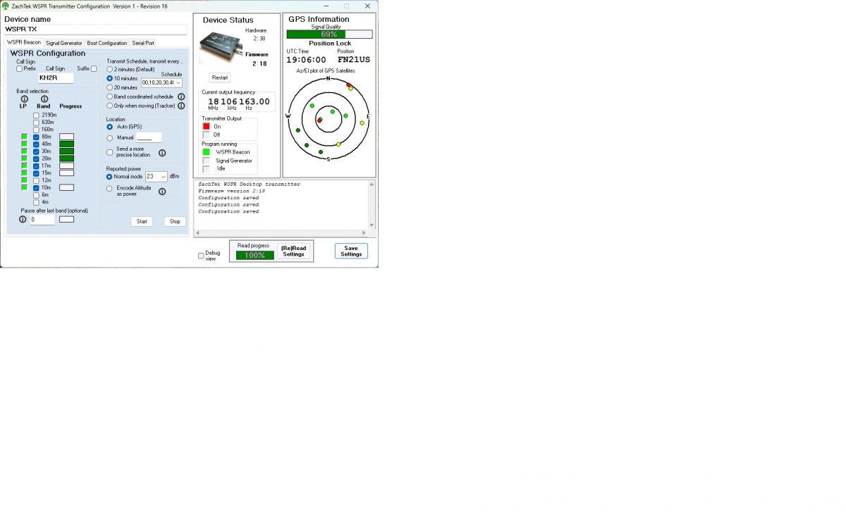
Here is a screenshot of the little Zachtek desktop WSPR beacon transmitter I bought. This is a great addition to the toolbox and works well for testing the radiation efficiency of an HF antenna. It has a GPS antenna input for timing and location reference. The frequency bands are selectable if you are testing a mono-band antenna. It will work into a fairly poor load, so I suggest sweeping the antenna first with an analyzer.
Zachtek configuration web interfaceWSPR beacon, 0.2 watts
This shows that my signal is getting out. So far, the furthest distance is 17,030 km with an SNR of -10 (Australia, VK5ARG). That is quite amazing when you think about it. I am letting this run overnight to see how the propagation changes. Overall, this was a good recreational project and now I have a known working HF antenna.
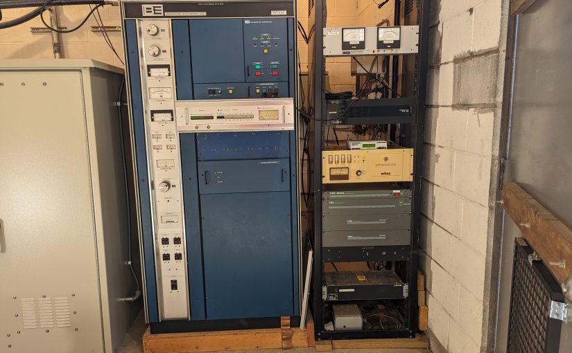
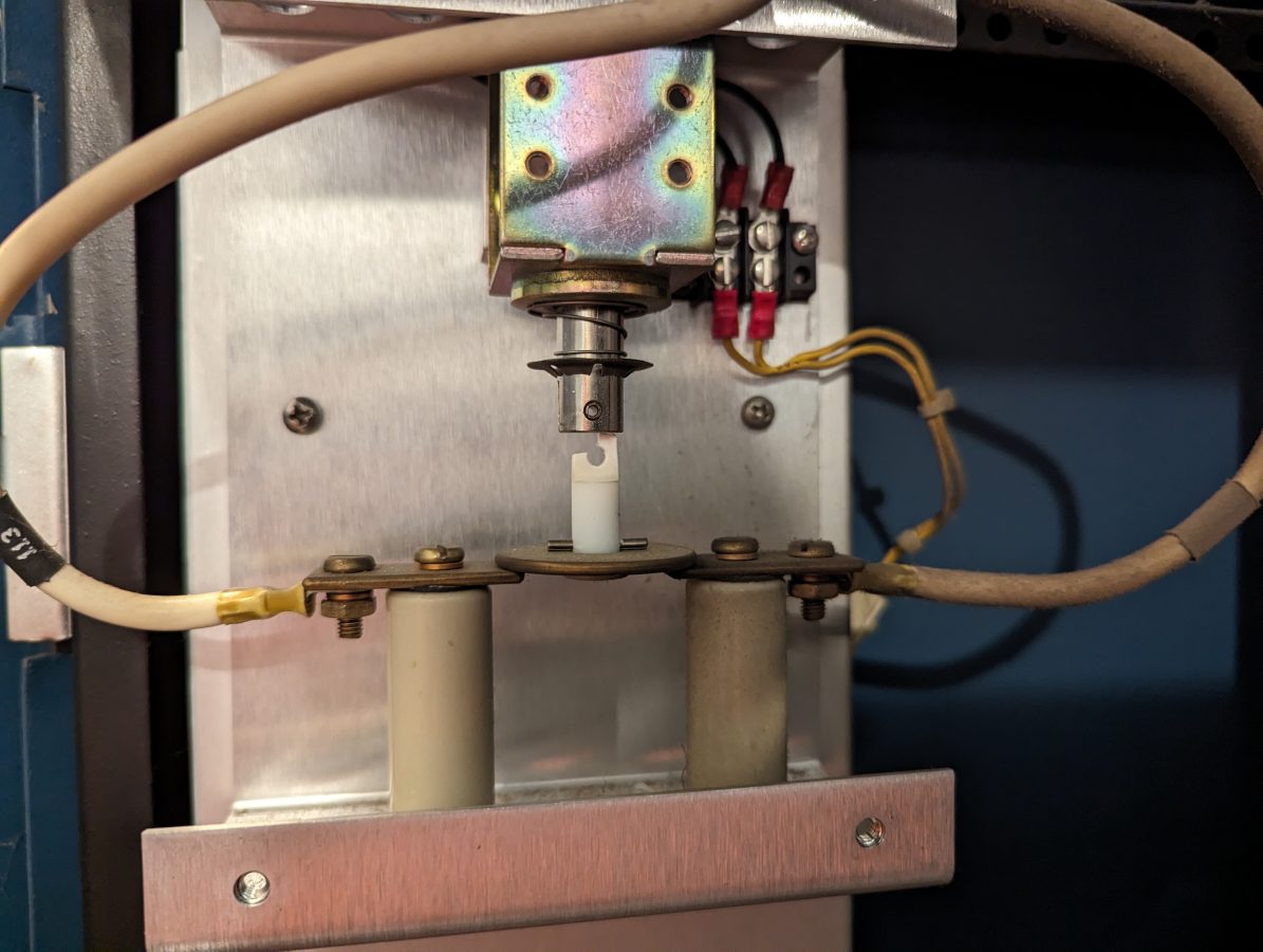
This Broadcast Electronics FM3.5A is 40 years old. There was a small problem that took the station off the air for a couple of hours this morning. The high voltage shorting solenoid fell apart, causing the 40 amp breaker in the service panel to trip.
BE FM3.5A defective shorting solenoid
These types of failures will become more frequent as the transmitter ages. Things like air switches, blower motors, tuning and loading mechanical assemblies, circuit breaker fatigue, plate rectifiers, screen and plate bypass capacitors, exciter and controller fans, etc. The list of potential failure points can get quite long. The fact is, nothing lasts forever.
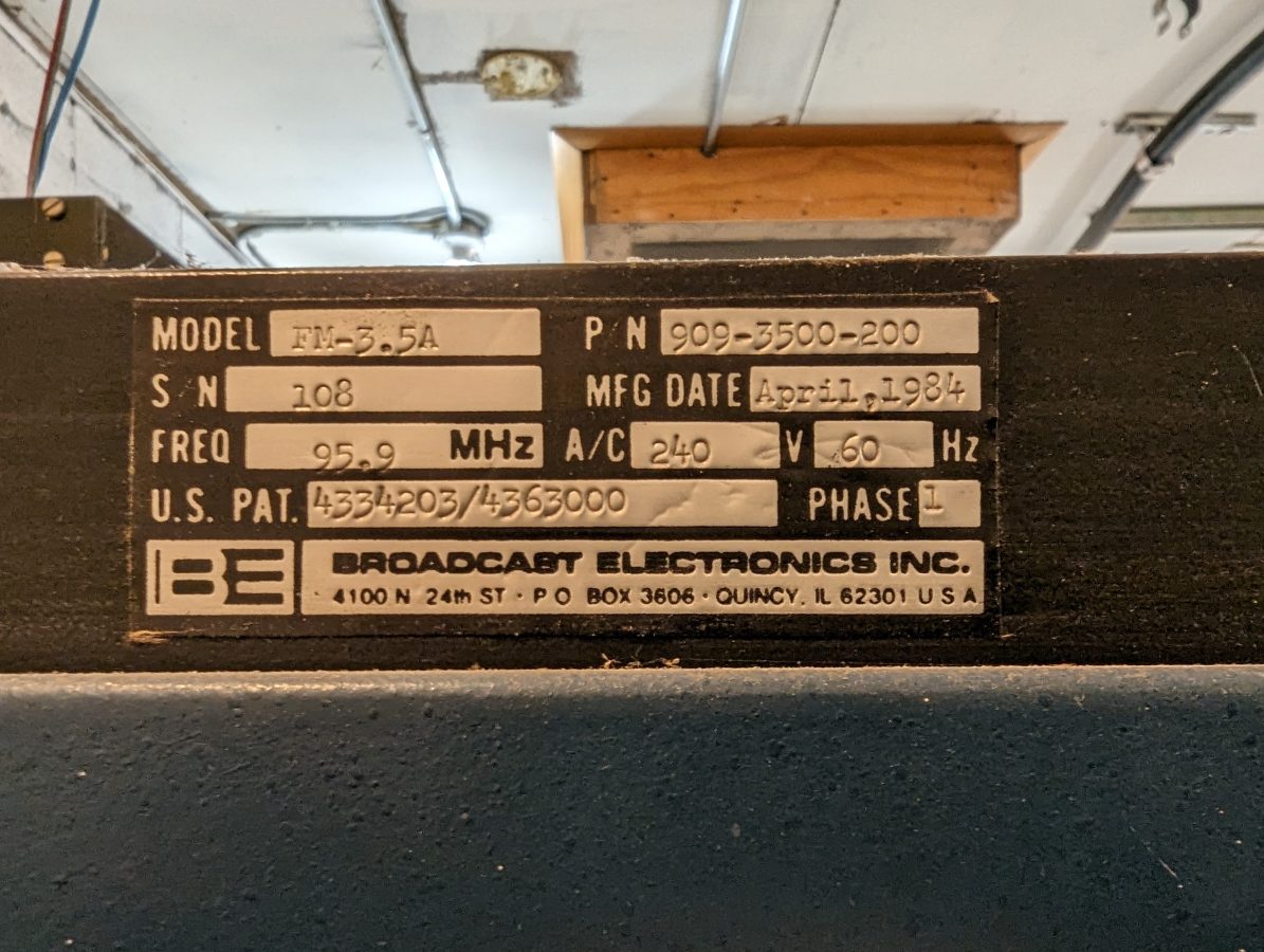
Manufacturers nameplate
There is no backup transmitter for this site and there is no easy way to get a temporary unit on line, if needed. This is not the oldest main transmitter that we service with no backup. That honor goes to a CCA DS-3000 built in 1970.
The question is; how long should old tube transmitters be kept in service? Also; how long should we (an independent service company) agree to maintain them? The temporary solution for the above failure was to remove the broken shorting bar and turn the transmitter back on.
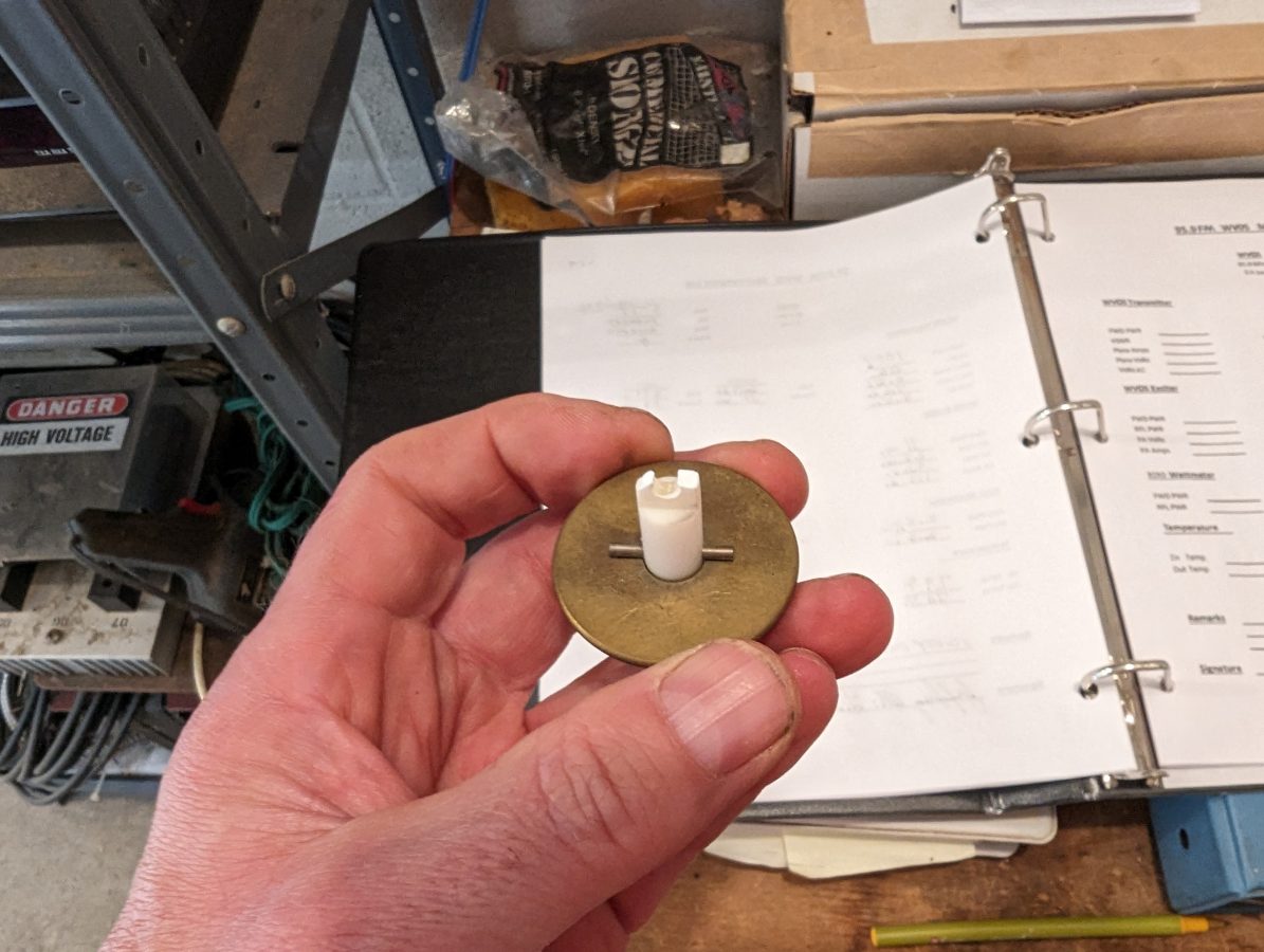
Broken shorting bar removed
That creates a safety issue for anyone who may need to work on the transmitter before the replacement arrives. It also creates a potential liability issue for my company.
I put a big label on the back door indicating that anyone doing service needs to discharge the power supply capacitor with the grounding stick (which they should be doing anyway). But I will feel better when the shorting solenoid is working again.
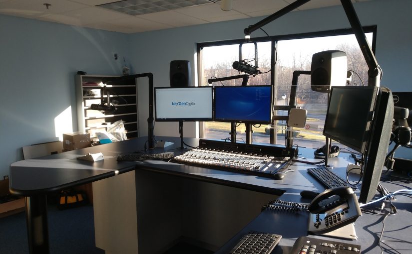
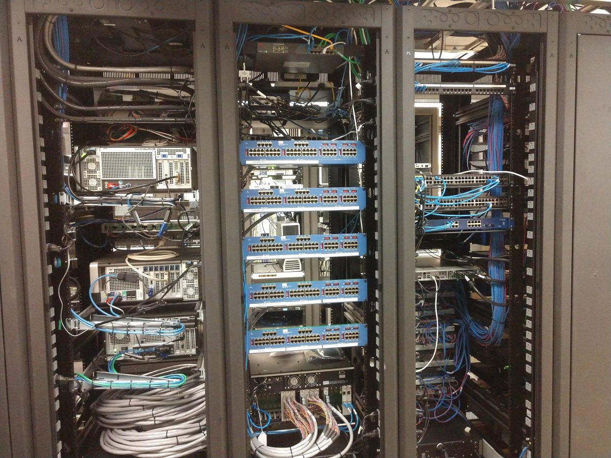
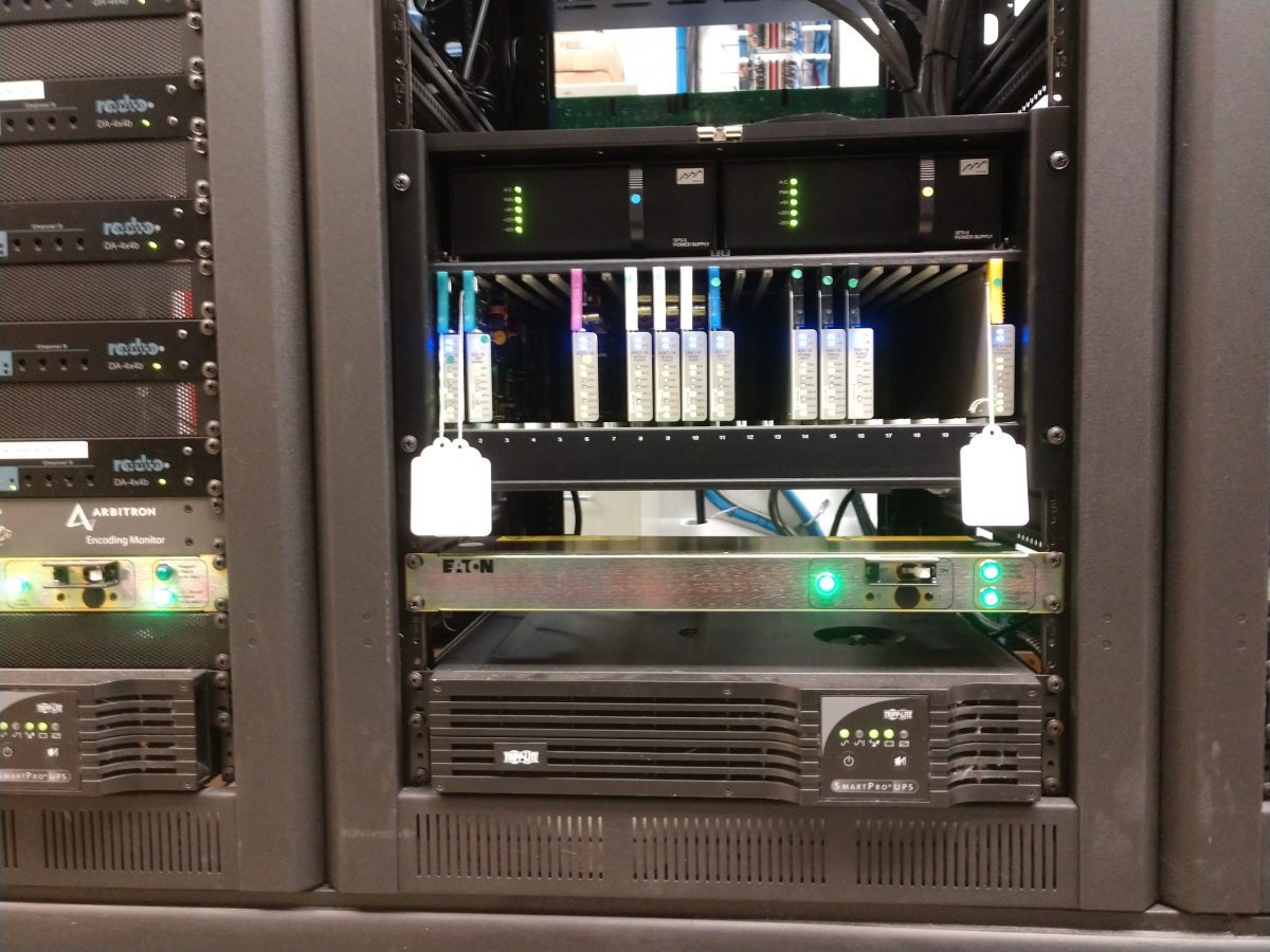
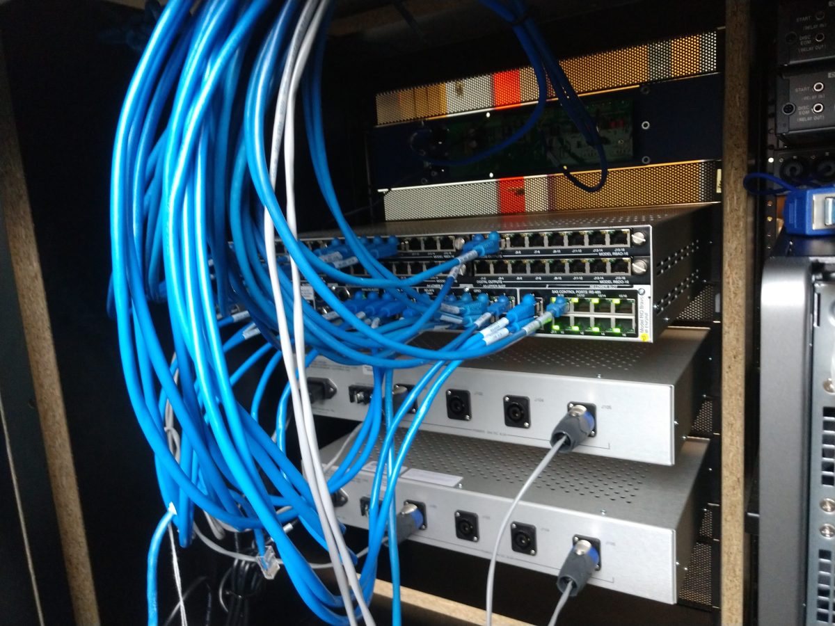
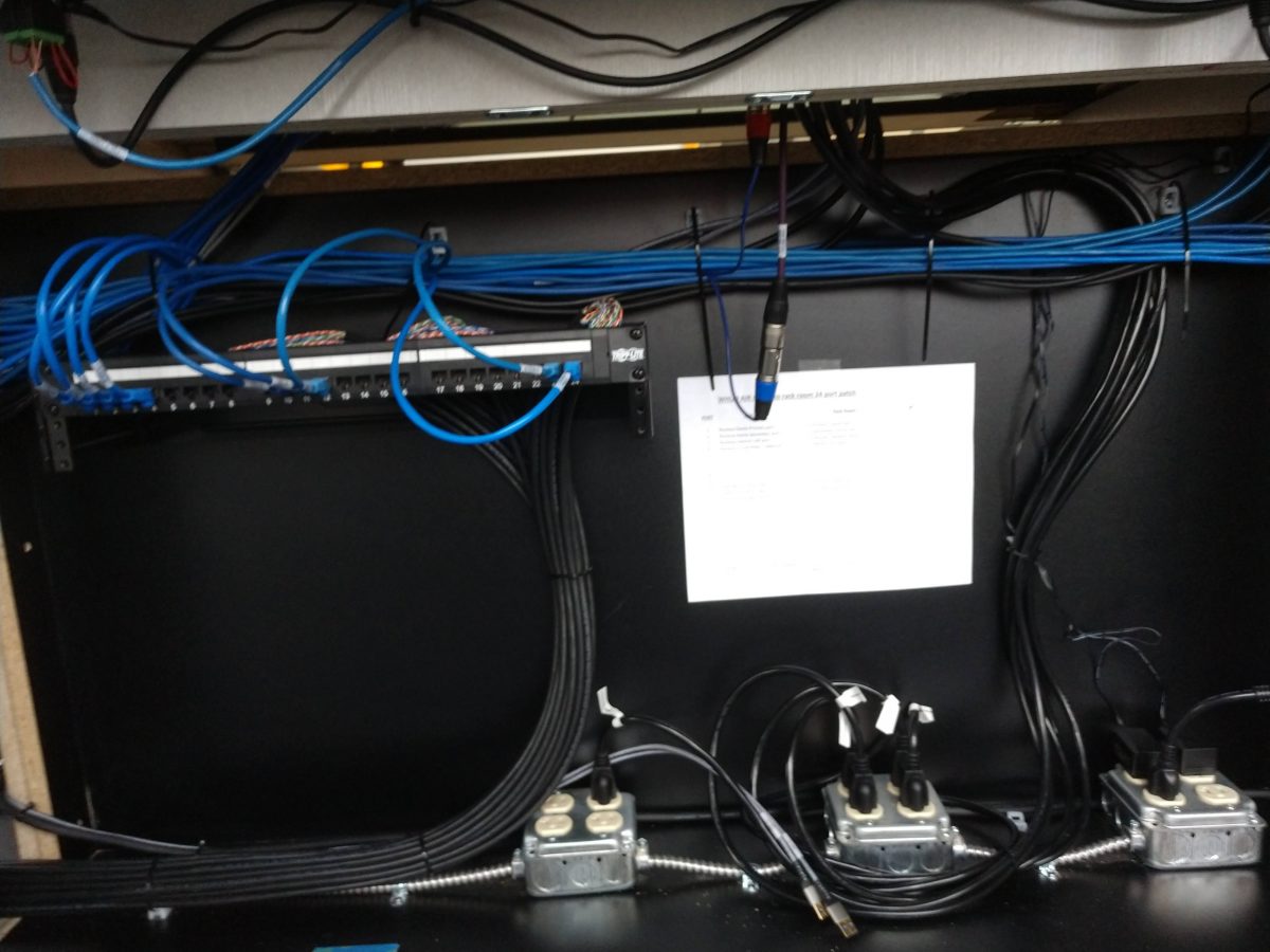
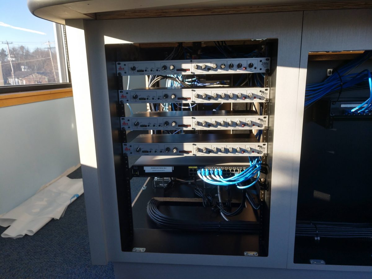
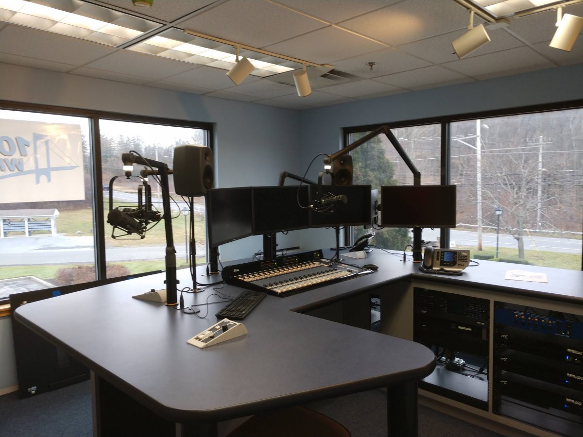
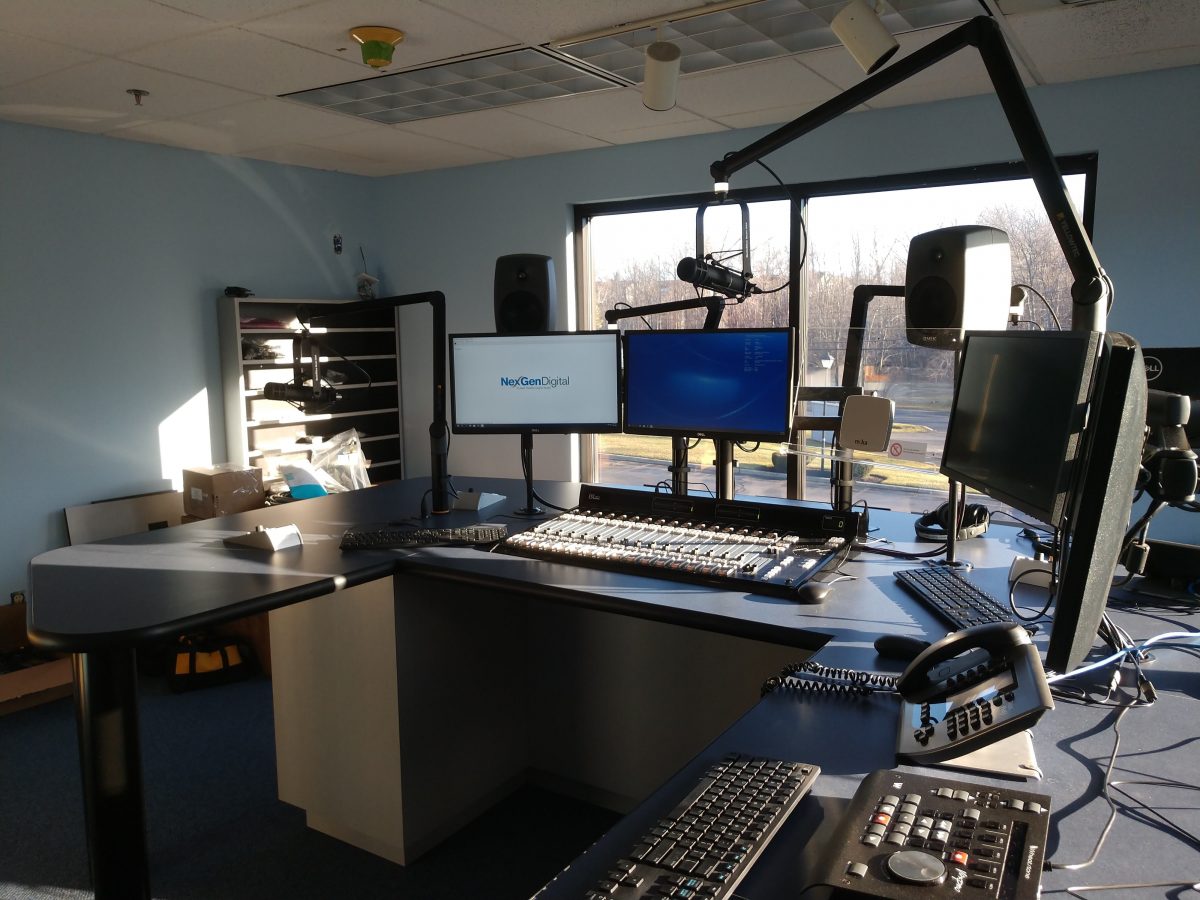
This is another SAS console installation for WHUD licensed to Peekskill, NY.
Rack Room wiring, 32KD router for WHUD and WSPKSierra Automated Systems 32KD routerSAS Gear; RIO BravoEthernet patch panel and trunk wiring to rack roomNetwork Switch and mic preampsRubicon Console, Studio Technologies FurnitureJust prior to going on the air